References
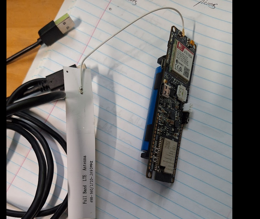
The Lily
There are heaps of models. Mine is 7670-R2-SA. SA is South America (also Australia). R2 is maybe revision 2?
First Steps
- Following “Quick Start” in Docs on Github
- Initially starting on Windows – let’s see
- Installed PlatformIO, Python, Visual Code
platform.inihas correct settings- Starting with ATDEbug example
- Compiled (tick) OK after a few tries (!)
- Upload (arrow)
- Error: cannot open port
- Fix: use a higher quality USB3 cable (now visible in VS as “COM7” enhanced serial )
- Start VS Serial monitor and set to COM7 115200 baud (as per sketch)
- Press reset button and … action! Sketch runs.
- Type
ATin the serial monitor to send it a command. - Problem: No line ending provided by serial monitor
- Fix: Ensure Line ending is “CR”.
- Great, we get
OKis response! And can run some other AT commands. No SIM yet…
Okay, so far, so good. Let’s get a SIM and try to connect to the Internets and then HTTP GET and POST stuff…
Getting Connected…. and fail
- Add a SIM card. Needs to be nano.
- Can query with AT commands
- Upload “HttpsBuiltInGet” to try to connect Internet and GET
- Error: NO SERVICE, Online
Hmmm… bit of a fail here. Let’s understand a bit about AT command and modems.
RTMF… and succeed
References:
Modems like the SIM7670 work via “AT” commands. Read an intro.
TinyGSM is a C++ library for Arduino/ESP32 which issues AT commands behind the scenes, enabling modem->init() type calls in your code. Nice!
( esp_modem is a possible, unexplored, alternative. )
However, for debugging and learning, started with AT directly. Use the sketch from lily, AT_Debug program, which used a fork of TinyGSM (more on that later). This program (from the LilyGo github) nicely sets up pins, #define -ing a skeleton to get things ready for input.
That fork thing? It means updates to TinyGSM are not used. An old bug caught me.
Let’s use direct AT commands to understand the problem:
rst:0x1 (POWERON_RESET),boot:0x12 (SPI_FAST_FLASH_BOOT)
Start Sketch
Trying baud rate 115200
Modem responded at rate:115200
***********************************************************
 You can now send AT commands
***********************************************************

AT
OK
AT+CSQ
# Signal rssi=19
+CSQ: 19,99
OK

PB DONE
AT+CGREG?
# 0=no network?, 11=emergency only
+CGREG: 0,11

OK

+CGEV: MDE ETACH

# fails even after a long time
AT+CGREG?
+CGREG: 0,0

# correct
OK
AT+CFUN?
+CFUN: 1

# change to LTE only (not 2=auto) and reset
AT+CNMP=38
OK

# reset and try
rst:0x1 (POWERON_RESET),boot:0x12 (SPI_FAST_FLASH_BOOT)
AT+CSQ
+CSQ: 21,99

OK
AT+CGREG?
# With LTE (set via AT+CNMP=38), connection is now "forbidden" not 11: "emergency only"
+CGREG: 0,3

OK
AT+CSQ
+CSQ: 21,99

# current operator: 0=automatic, 2=numeric, 50501=telstra,7=EUTRAN (???)
# ok
OK
AT+COPS?
+COPS: 0,2,"50501",7

OK
AT+COPS=?
+COPS: (1,"Telstra Mobile","Telstra","50501",7),(3,"Optus AU","Optus","50502",7),(3,"vodafone AU","voda AU","50503",7),,(0,1,2,3,4),(0,1,2)

# Wait a few minutes
# Network changes from 3 (denied) to 11 (emergency)
AT+CGREG?
+CGREG: 0,11

OK

AT+CSQ
+CSQ: 21,99

# Check bands  <mode>[,<lte_mode>][,<lte_modeExt>]
+CNBP?
+CNBP: 0X0000000000280180,0X00000000080000DF,0X0002
# check bitwise operators on datasheet
# LTE BANDS ARE: 1,2,3,4,5,7,8,28 as per datasheet on lilygo and
# 0X0002 means band66 as per datasheet
# so: as expected


AT+CGDCONT?
+CGDCONT: 1,"IP","Internet","",0,0,,,,

OK
# **this is incorrect (should be telstra.internet!)**

# set to APN correctly
AT+CGDCONT=1,"IP","telstra.internet","",0,0,,,,

# Reset and it connects!
AT+CRESET
OK
*ATREADY: 1
+CPIN: READY
SMS DONE
+CGEV: EPS PDN ACT 1
+CGEV: ME PDN DEACT 8
PB DONE
#  "1" means registered
+CGREG: 0,1
Some notes on the above:
- Check the bands with this script which parses “0X00000000080000DF” into something meaningful
- Set mode to LTE (not automatic).
- Definitely necessary to set APN correct!
- TinyGSM (forked version 0.11.7) sets the APN on the first run, but does not update it!
Right, we are connected, let’s do some HTTP
Now that the APN is set correctly, we can run some examples from LilyGo/TinyGSM.
Some example set modem.setNetworkMode(MODEM_NETWORK_AUTO) which didn’t work for me. As noted above, change this to modem.setNetworkMode(MODEM_NETWORK_LTE).
- HttpClient: get a webpage. OK
HttpsClient: is not HTTPS (!) as far as I can see! Fake news?- HttpsBuiltInGet: OK. Can handle https it seems. We need this for database reads.
- HttpsBuiltInPost: OK. Great – we’ll need this for database writes.
- GPS_BuiltIn: FAIL. No GPS functionality on this board. It’s available in another (see LilyGo).
- DeepSleep: Not sure, need to understand esp + modem sleeping
- esp_modem: test this instead of TinyGSM.
Although Bluetooth and Wifi are in TinyGSM library / LilyGo examples, I don’t think this board supports them.
Hey, there’s a battery holder
(Nothing to do with the modem, but can power the whole thing.)
Oh yeah, on the back. Whack in a battery and turn the (battery) switch on. Run the BatteryLevel example. We need to disconnect the USB to get a true reading. But then we can’t see the serial output!
The example writes via Wifi (via esp32) and writes to a UDP server:port. Run a little udp echo server and we see:
Battery:4176mV  Solar:0mV
Battery:4176mV  Solar:0mV # removed
Battery:3990mV  Solar:0mV
Battery:4022mV  Solar:0mV
We see the USB was unplugged and voltage is now battery voltage. It’s running on battery and 4G. That’s cool. In the photo below it’s running on battery, connected to wifi (but 4G available) and reporting battery voltage.
Connecting a simple solar panel @5VDC didn’t show up on the reading (?) but did light up an LED. There appears to not be a ADC on the solar pin because BOARD_SOLAR_ADC_PIN is not defined/
No sure from the docs if USB charges the battery. Let’s run a simple test.
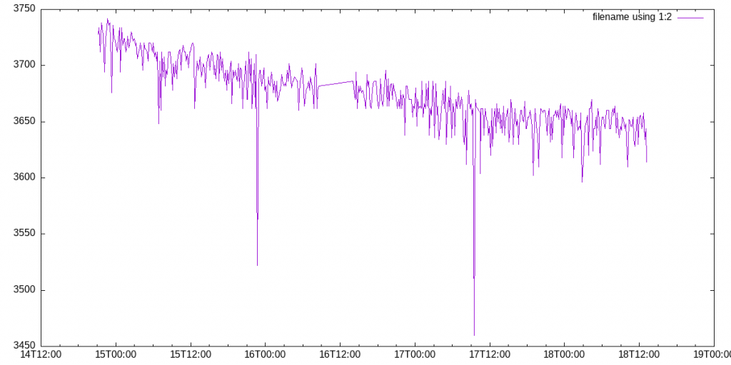
First, run with battery only:
2024-01-12T17:40:00 Battery:4040mV
2024-01-12T18:35:55 Battery:3994mV
2024-01-12T20:30:55 Battery:3894mV
2024-01-13T08:30:44 Battery:3624mV
That’s 400mV drop over 14 hours, or 30mV / hour. Assuming usability voltage of 4V to 3.4V (that’s 600mV) or 21 hours. Call it a day. And indeed at 24hr voltage was 3.3V. That’s with a wifi connection, transmitting once a second. Roughly, we can do 4 minutes work a day and get a year’s runtime.

So battery is flat (3.3V). I plugged in the USB for a few hours. Did it blend charge? At 12:00:00 it was 3350mV and then two hours later it was 3700mV. I checked this wasn’t superficial charge but running a bit. So yeah, USB charges battery.
I’m sleepy
Can we easily use this thing to make remote monitoring devices or maybe take photos? We wanna deepsleep for (e.g.) 10 minutes, wake up and do a thing, then sleep again. So that’s 144 wakeups per day. Say 10s work on average, giving 60 days runtime if deepsleep is close to zero power. In theory.
Let test that, with a program that:
- wakeup (from deepsleep timer)
- connect to 4g
- write the battery voltage to a server
- deepsleep for 10 minutes
Maybe we should average that millivolt reading! But roughly, over 50 hours we drop 50mV. That’s 1.0mV/hr. With 600mV range, that’s 25 days. That’s less than 60 days but in the ballpark. Probably deepsleep uses some non-trivial power (to test) and the 4G connection will likely be more hungry than wifi.
Another way of looking at it is about 0.15mV/send. Or 4000 sends over 600mV range. Or hourly for 6 months. That’s ignoring deepsleep energy.
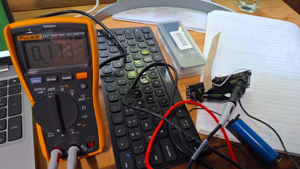
ps. I need a milli/micro ampmeter to test deepsleep current. A logging unit would enable total Ah/wakeup. My multimeter is rubbish.
Ok, I got a proper multimeter (Fluke 117). Send takes about 15s and meter shows about 100mA. With a 2000mAh 18650 battery that’s 4800 wake-and-sends. Great – that agrees with 4000 sends, via mV method.
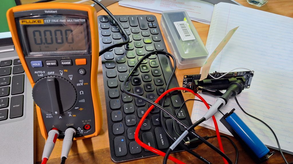
Deep sleep on the meter reads as <1mA (i.e. out of range of accuracy). Call it 0.250mA. That’s 8000 hours sleeping or a year.
So, putting this all together and assuming our operation-to-do is fast / lowish energy, expect:
- 4 months operation, hourly send
- 8 months operation, 6 hourly send
- 10 months operation, daily send
This is on one average 18650 battery (2000mAh).
More stuff
Other stuff to explore
- Use Http(s)BuiltInPost to write data to Influx
- Use Http(s)BuiltInGet to run a last data query on Influx
- Check https connections are actually secure
- Use the SDCard
- Plug in a solar panel (4.4v – 6.0v, maybe needs a regulator) and see if it keeps running ….
Test deepsleep current.
Appendix : AT Commands
| command      | explain                              | Response     |
| ------------ | ------------------------------------ | ------------ |
| AT           | AT test instruction                  | OK           |
| AT+SIMCOMATI | version information                  |              |
| AT+CPIN?     | Example Query the SIM card status    | +CPIN: READY |
| AT+CGREG?    | Network Registration Status          | +CGREG: 0,1  |
| AT+CSQ       | Network signal quality query         |              |
| AT+COPS?     | Querying current Carrier Information |              |


# Set APN
AT+CGDCONT=1,"IP","telstra.internet","",0,0,,,,

# 2: ENABLE ERROR RESULT WITH VALUE
AT+CMEE=2

AT+CGREG
+CGREG: 0,3 #
        ^ ^
	| |- rego denied (1=registered) (11=emergency only)
        |- 0-2 : unsolicated result code (0=don't report)

# Get service provider name from SIM
AT+CSPN?
+CSPN: "Telstra",0

# Reset factory default (unsure if this is a COMPLETE reset)
AT&F